Hello Everyone, I bring to you a tutorial on how the AVR TWI module operates. This is part 1 of the tutorial and deals with Master Transmitter and Master Receiver mode. Stay tuned for part 2 which will build on this to add Slave Receiver and Slave Transmitter functionality.
I2C (Inter Integrated Circuit) or TWI (Two Wire Interface) is a half duplex serial two wire interface for interconnecting low to medium speed peripherals. It uses two open drain signal lines, Serial Data (SDA) and Serial Clock (SCL). As these are open drain lines the device may sink however it cannot drive a line high. In order to allow for high signals the lines must be pulled high using a pull-up resistor. The bus drivers of all TWI compliant devices are open drain and this is essential to the operation of the interface.
TWI is a master/slave protocol. Multiple masters are allowed however only one device may be master at any one time.
The ATMEGA and ATTINY range of ATMEL MCU’s (along with the majority of other ATMEL MCU’s) have a dedicated TWI bus interface which takes care of START/STOP conditions, SCL clock, arbitration and address detection. They also have dedicated shift registers for sending and receiving data on the bus. The TWI pins also have slew rate limiting and a spike detection to remove spikes shorter than 50ns. The internal pull ups can be enabled by setting the PORT bits on the SDA and SCL pins to high.
I will first provide an overview of the TWI interface, followed by an overview of the AVR TWI hardware before I get into designing the interrupt driven TWI library.

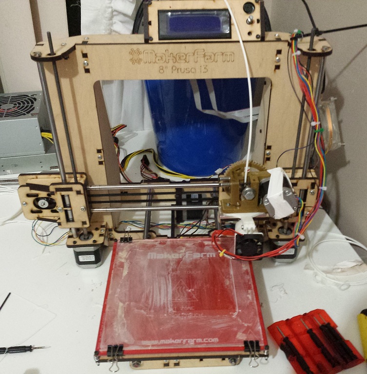
 Desktop 3D printers have come a long way in the past several years. The RepRap community provides open source designs for Fused Deposition Modelling printers. This makes it possible to construct a high quality desktop 3D printer for under $1000