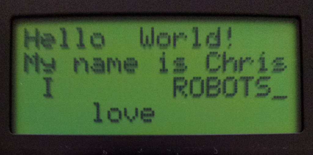
I would like to add an alphanumeric display to my AVR projects. I picked up this FDCC1604A 16×4 alphanumeric display from RS components.
I now require a library to simplify use over a variety of ATMEL based applications.
 FDCC_LCD.h
These alphanumeric displays are controlled using a parallel bus which can operate in either 4-bit or 8-bit mode, with three control signals RS, RW and E
| Signal Pin | Values | Description |
| RS – Register Select | HIGH – Write to register LOW – Send Command |
When in write mode, set this pin high to write to DDRAM or CGRAM, otherwise write data on the data bus will be interpreted as a command |
| RW – Read/Write | HIGH – Read mode LOW – Write mode |
Set high to read data form the bus and low to write data (send data or a command) |
| E – Enable | HIGH – Can send and receive data LOW – LCD can process data |
The LCD controller can only process data when the enable pin is not pulled high. In order to send data or a command, must first ensure that the LCD is not currently busy, then pulse the enable pin with data on the bus and RS and RW pins set accordingly. |
I require several criteria for the library;
- Expose as much functionality of the LCD as possible
- Be able to individually set the pins of the MCU to correspond to pins of the LCD with minimal programming to change
- Allow for either 4-bit or 8-bit bus mode
- Work for any FDCCxxxxx model display. My code will conform to the data sheet of all of the displays, however I will be satisfied when it works for a FDCC1604A and a FDCC1602B as they are all I have available to me
Switching between 4-bit mode and 8-bit mode is a matter of commenting or un-commenting the LCD4bit define in the header. If this define is included then all
functions will be adjusted to work in 4-bit mode. This allows the same function set to be used for both 4-bit and 8-bit mode.
|
1 2 3 4 5 6 7 8 |
// Uncomment this define to use 4bit LCD interface #define LCD4bit // ----------------------------------------------- #ifdef LCD4bit #define DATA_MODE 0 #else #define DATA_MODE 1 #endif |
I have also created a set of defines In order to individually set which pins of which ports connect to the LCD, simply set the port letter and pin number in these defines:
|
1 2 3 4 5 6 7 8 9 10 11 12 13 14 15 16 17 18 19 20 21 22 23 24 25 26 27 28 29 30 31 32 33 34 35 |
/* Define the pin numbers of each connection */ #ifndef LCD4bit // Only need to define the four LSB if in 8 bit mode #define LCD_D0_PIN 0 #define LCD_D1_PIN 1 #define LCD_D2_PIN 2 #define LCD_D3_PIN 3 #endif #define LCD_D4_PIN 4 #define LCD_D5_PIN 5 #define LCD_D6_PIN 6 #define LCD_D7_PIN 7 #define LCD_RS_PIN 0 #define LCD_RW_PIN 1 #define LCD_E_PIN 2 /* Define the port letter of each of the connections */ #ifndef LCD4bit // Only need to define the four LSB if in 8 bit more #define LCD_D0 A #define LCD_D1 A #define LCD_D2 A #define LCD_D3 A #endif #define LCD_D4 A #define LCD_D5 A #define LCD_D6 A #define LCD_D7 A #define LCD_RS B #define LCD_RW B #define LCD_E B |