 Desktop 3D printers have come a long way in the past several years. The RepRap community provides open source designs for Fused Deposition Modelling printers. This makes it possible to construct a high quality desktop 3D printer for under $1000
using only a small number of specialized parts (ie. filament extruder components).
3D printers introduce the possibility of fabricating precision parts in a timely and – most important – reliable manner. What would usually take hours to fabricate in the workshop can now be printed, still in a couple of hours, however all that need be done is draw a design in your favorite CAD program and send it off to print.
My love of mechatronics not only attracts me to the 3D printer itself, but the many possibilities for design and prototyping that it opens! For several years I have been building my RepRaps. Or I guess I should say RepStrap. I have been through a couple of Mendel variations which ended up leading me to a custom i3 design. At the end of exam period 2013 however I decided that I would go ahead and pull my existing printer apart and reassemble it into a delta design. So after printing all of the parts and being sure that I could assemble it first try – I went for it. That was a mistake. Several parts were missing and when attempting reassemble my i3 I broke a z-carriage. So now I was left with a broken printer, no spares and no printer to print a spare. Lesson learned – ALWAYS have a full set of spares – especially if you are planning on completely disassembling your printer.
Well, I print everything. So many useless robots that have a lifespan of a week before they are torn apart harvested for their components and a new one is printed. So I may aswell just bite the bullet and spend some money and get a kit, right?
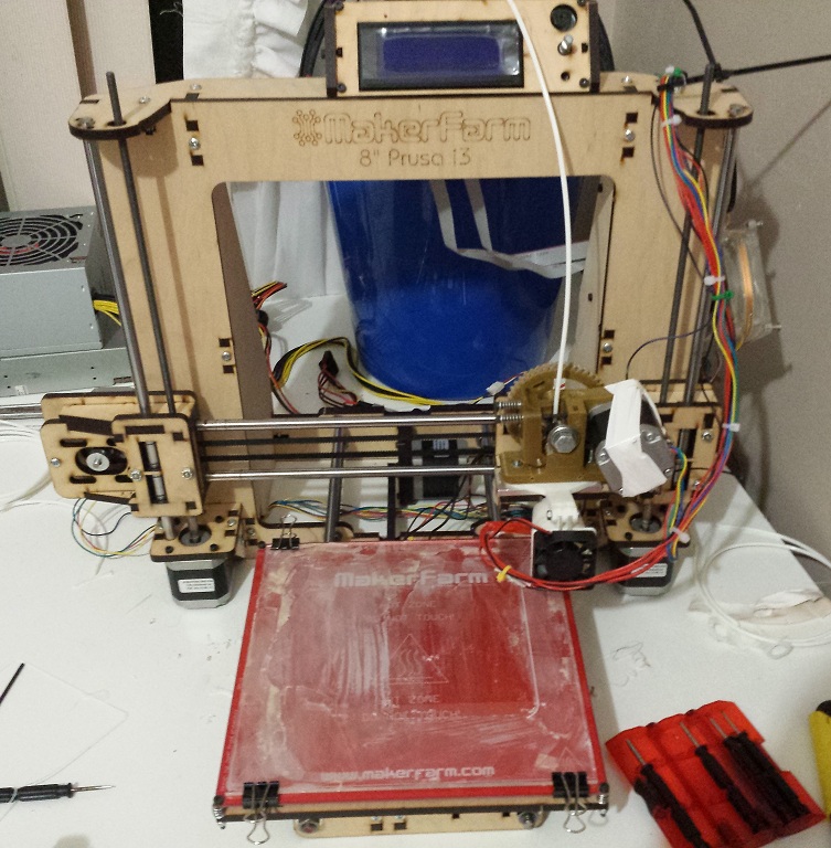
After extensive research into the many RepRap designs and kits out there, I decided on the wood base Prusa i3 from MakerFarm.
Assembly & Testing
The laser cut wood frame from the guys over at MakerFarm makes assembly a breeze, analogous to assembling a small lego kit and really satisfied some burning nostalgia. Following the short YouTube tutorials for each piece, assembly took just over an hour, followed by another hour for electrical wiring and cable management (only because I checked and double checked every wire before powering up, I don’t want to have another broken printer on my desk).
The ONE issue I encountered during assembly was in attaching the extruder block to the x-carriage. Here, some bolts used to assemble the carriage sit in their bolt trap such
that edges protrude a couple millimetres higher than the base of the x carriage. This prevents the extruder block from sitting flat against the base.
Filing these down solved the problem.
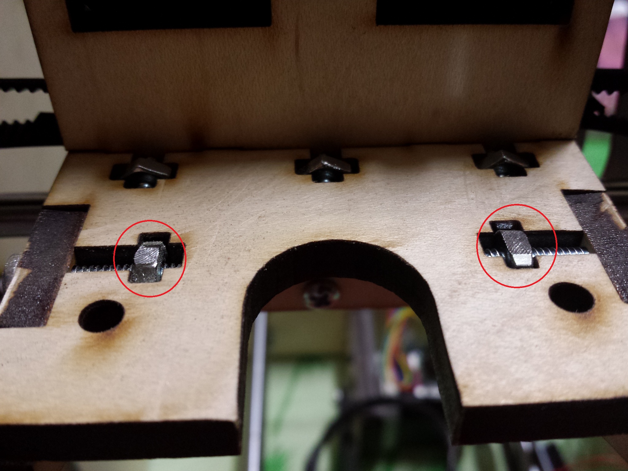
Nuts had to be filed down to allow extruder block to fit.
After assembly, I encountered another issue that I would like to warn others about. RAMPS requires a 5A and an 11A 12V supply rail (or just a single 16A rail). Although the ATX power supply I obtained from my local computer store is rated for an 8A and a 14A rail, actual outputs were more like 4A and 9A. Many suppliers, particularly those cheap off-brand suppliers, may rate their products according to their performance under optimal conditions. So sure the supply may be able to put out 14A and 8A, however this is under optimal conditions and probably for only milliseconds.
The consequence of this insufficient power supply was that I was unable to reach hot end temperatures above ~210°C and HBP temps above ~80°C.
Despite these cold temperatures and several failed attempts, my first calibration cube test was a success!
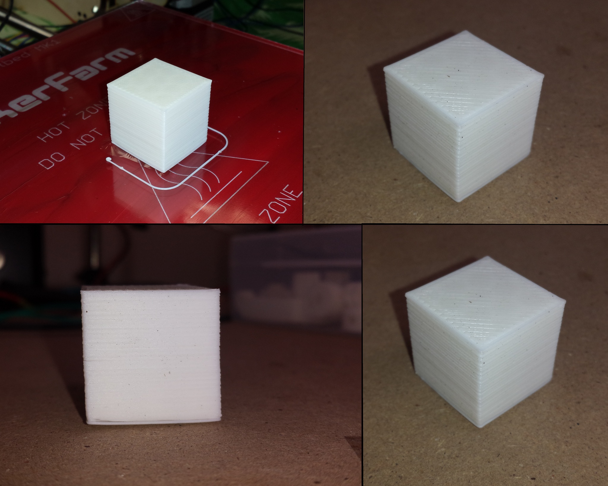
My first calibration cube
Pictured above is my first calibration cube, several failed attempts can be attributed to a poor build surface in which the piece would come loose after just a few layers.
The recommended hair spray method was not working, perhaps I was using the incorrect hair spray, perhaps the HBP was too cold. Adding a thin layer of ABS slurry to the glass solved this problem.
Calibration
The calibration cube showed some layer separation and warping on the lower layers. The warping is certainly to be expected when printing ABS with an insufficient HBP temperature. The layer separation however was found to be a result of a poorly homed z axis (although a 210°C extruder likely added to the problem). Some finesse, patience and my 2 micron feeler gauge later and the z axis was homed properly.
Printing larger objects such as the calibration cube, extruder parts and parts for my DELTA robot went well using the calibration parameters preloaded in MARLIN from the guys at MakerFarm. No tweaking of the axis or E-Steps was necessary, however after attempting to print at considerably higher resolution for some revolute joints for DELTA, it became apparent that extrusion rates were not optimal. The imaged below show some obvious over-extrusion for small surface areas:
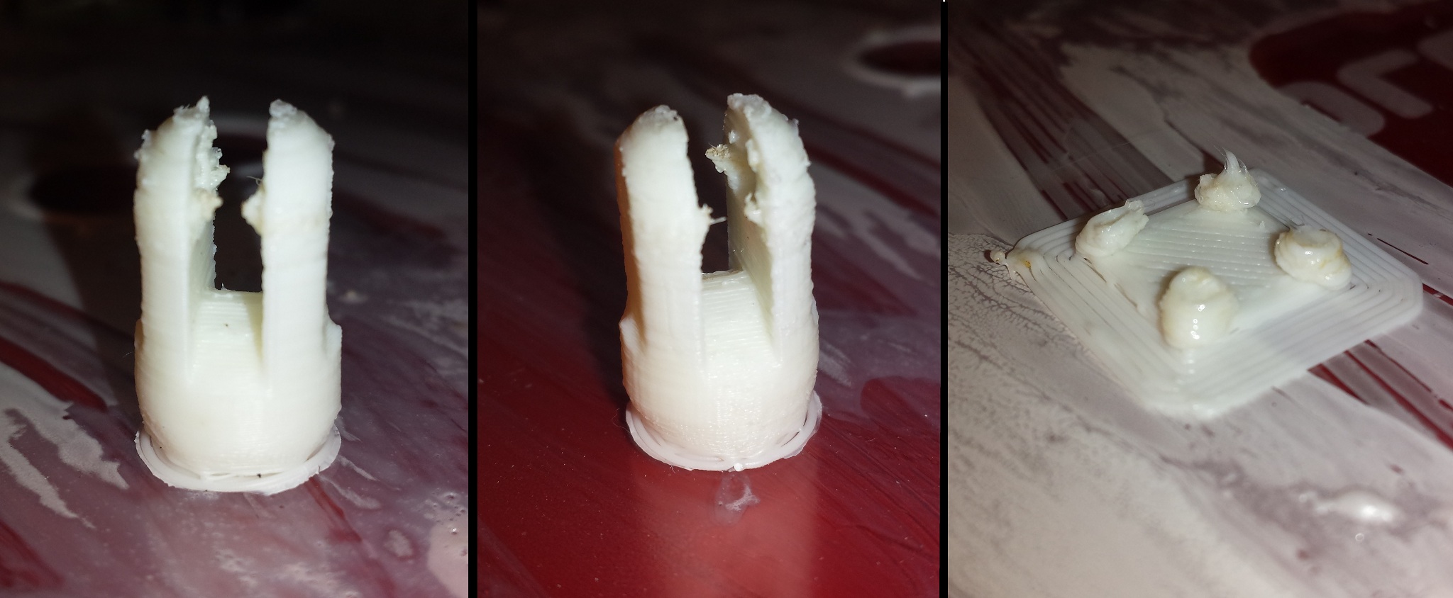
Over extrusion on small surface areas.
- LEFT: A revolute joint piece, over extrusion is seen at small cross section area near hole.
- MIDDLE: Another revolute joint piece, over extrusion is seen at same location.
- RIGHT: A test calibration pyramid from thingiverse. Print was stopped as it was obvious it would not finish.
Following Triffid Hunter’s extrusion calibration guide on the RepRap wiki, I was able to find an extremely accurate E-Steps value of 875.5 steps/mm.
Magma Hot End Clogs
After replacing my power supply with one that can provide sufficient power to heat up the hot end and heat bed, I began having continuous clogs in my magma hot end.
It is very important to ensure a fan is on an all metal hot ends at all times, however with the magma hot end (and perhaps with other all metal hot ends, magma is all I
have used until my E3D gets here) the fan must be cooling just the right spot. If too far down the stem is cooled then filament will solidify and cause a clog, however
if the fan is NOT aimed down far enough, then when not extruding, the upper section will heat up and melt. When extrusion begins colder filament will be pushed in and the top part of the stem will block.What I found is that when I loaded the filament into the extruder, it would extrude fine, however after ~20 seconds of being idle a clog would occur.
It took some trial and error to kapton tape a small piece of metal between the bottom of the fan and different positions on the hot end heat sink in order
to divert the cooling to the correct level. Once the sweet spot was found and printing became possible, immediately a fan shroud was printed as a more permanent solution
(don’t you lust love the concept, using a 3D printer to fabricate a part to fix the 3D printer that printed it).
Summary
So there it is, my MakerFarm Prusa i3 is up and running. Not sure if I will still pursue the Delta design, it was mainly a novelty because I was working on a very large Delta robot for my final year thesis. All in all I am happy with this design for now. I think I will keep it around without needing too much mods until I can afford to build myself a dual extruder.