Hello Everyone, I bring to you a tutorial on how the AVR TWI module operates. This is part 1 of the tutorial and deals with Master Transmitter and Master Receiver mode. Stay tuned for part 2 which will build on this to add Slave Receiver and Slave Transmitter functionality.
I2C (Inter Integrated Circuit) or TWI (Two Wire Interface) is a half duplex serial two wire interface for interconnecting low to medium speed peripherals. It uses two open drain signal lines, Serial Data (SDA) and Serial Clock (SCL). As these are open drain lines the device may sink however it cannot drive a line high. In order to allow for high signals the lines must be pulled high using a pull-up resistor. The bus drivers of all TWI compliant devices are open drain and this is essential to the operation of the interface.
TWI is a master/slave protocol. Multiple masters are allowed however only one device may be master at any one time.
The ATMEGA and ATTINY range of ATMEL MCU’s (along with the majority of other ATMEL MCU’s) have a dedicated TWI bus interface which takes care of START/STOP conditions, SCL clock, arbitration and address detection. They also have dedicated shift registers for sending and receiving data on the bus. The TWI pins also have slew rate limiting and a spike detection to remove spikes shorter than 50ns. The internal pull ups can be enabled by setting the PORT bits on the SDA and SCL pins to high.
I will first provide an overview of the TWI interface, followed by an overview of the AVR TWI hardware before I get into designing the interrupt driven TWI library.
The Code:
If you just want the code to use, download it here:
 TWIlib.c
Basic Transmission of Bits
Each data bit over the line is transmitted during a high SCL pulse, the bit should be stable on the data line BEFORE the SCL line is pulsed high and may only change AFTER the SCL line goes low. Thus the data line must remain static for the duration that the SCL line is HIGH, the exception to this rule is when generating a START or STOP condition as explained in the proceeding section.
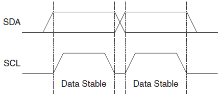
Data bit transmission during CLK HIGH pulse – Image from ATMEGA datasheet
A TWI packet is 9 bits long; a data packet consists of one 8-bit data byte and one acknowledgement bit; an address packet consists of one 7-bit address, one R/W bit and one acknowledgment bit.
The clock rate is set by the Master, however handshaking between Master and Slave can be achieved using the open drain bus design. The Slave may extend the duration of the clock LOW period by holding the SCL line LOW if it requires more time for processing or if the Master clock frequency is too high.
Start/Stop Condition
When a Master would like to initiate a transfer and take control of the bus, it transmits a START condition. A START condition is transmitted by transitioning SDA from HIGH to LOW whilst the clock line is HIGH. When the transmission is finished and the Master would like to release control of the bus, a STOP condition is transmitted. A STOP condition is transmitted by transitioning SDA from LOW to HIGH whilst the clock line is HIGH. Between the START and STOP conditions, the bus is considered busy and no other Master should attempt to take control. If a Master would like to begin another transmission without relinquishing control of the bus (ie write a read address to a device and then perform a read operation), it can send a REPEATED START condition. This is a START condition sent between another START and a STOP.
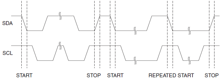
The START, STOP and REPEATED START conditions – Image from ATMEGA datasheet
The ACK and NACK Conditions
The final condition on the line to cover is the ACK and NACK bits. These are transmitted by the receiver during the ninth bit of the data packet. In order to transmit an ACK (acknowledged) bit, the receiver pulls the SDA line LOW for the ninth bit. In order to transmit the NACK (not acknowledged) bit, the receiver does not pull the SDA line low (hence it is pulled high via the pull up resistors). This allows a NACK bit to be transmitted intentionally by the receiver, or if the receiver stops responding/communication is severed it is also transmitted.
Addressing a Slave
A TWI device is addressed using a 7-bit data bit. Hence a total of 127 devices may be connected to a TWI bus, where the address 000 0000 is reserved for a broadcast to all slaves. When a start condition is detected, a slave will begin listening for an address, if the slave recognises the address being transmitted as its own then it will pull the data line low during the ninth clock cycle in order to acknowledge that it is listening (send the ACK). Following the address bits, a read /write bit is transmitted, this indicates if the slave should be set up to receive data (write operation, R/W = 0) or send data over the bus (read operation R/W = 1).
Some Terminology:
| Slave address + WRITE bit | SLA+W |
| Slave address + READ bit | SLA+R |
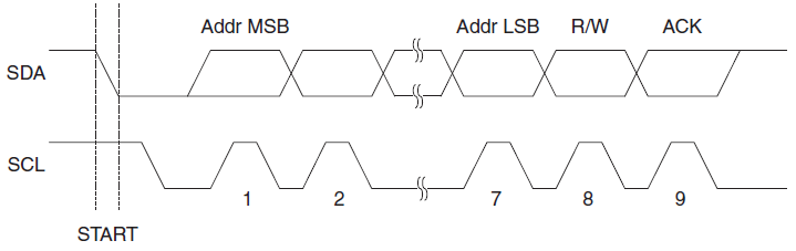
The structure of the address packet
Overview of AVR TWI Registers
Before I get into detail about setting up the TWI and designing the interrupt driven library, it is prudent to first give an overview of the TWI registers and the meaning of the the bits that I will be referring to later. For more detailed information obout these registers and the bits therein, head to the ATMEL website and download the datasheet for your device. The information I present here can be found in these datasheet, I just attempt to present in a concise and cogent manner. There are six 8-bit registers associated with the TWI, they are;
TWBR: TWI Bit Rate Register
| bit: | 7 | 6 | 5 | 4 | 3 | 2 | 1 | 0 |
| TWBR7 | TWBR6 | TWBR5 | TWBR4 | TWBR3 | TWBR2 | TWBR1 | TWBR0 |
The bit rate register allows a division factor to be set for the TWI clock. This division factor divides the CPU clock in order to set the SCL frequency according to the following equation:
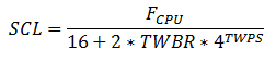
SCL clock frequency calculation
Where TWPS is a prescale bit (see the TWI status register TWSR)
TWSR: TWI Status Register
| bit: | 7 | 6 | 5 | 4 | 3 | 2 | 1 | 0 |
| TWS7 | TWS6 | TWS5 | TWS4 | TWS3 | - | TWPS1 | TWPS0 |
The TWI status register – as its name implies – contains the status of the TWI hardware along with the two prescaler bits which when combined with the TWBR register value are used to calculate the SCL clock frequency.
Bits 3:7 are the status code bits. As the register also contains prescale bits, a mask should be used when reading the status code.
|
1 |
status = TWBR & 0xF8 |
Bits 0:1 are the prescaler bits. The prescale value is a two bit binary number, giving it a value between 0 and 4. This prescale value is the exponent to a base of 4 in the SCL frequency calculation. Hence these prescale bits can be used to generate values of:
| TWPS0 | TWPS1 | Prescaler Value |
| 0 | 0 | 1 |
| 0 | 1 | 4 |
| 1 | 0 | 16 |
| 1 | 1 | 64 |
Bit 2 is read only and had an initial value of 0 – hence is always 0.
TWCR: TWI Control Register
| bit: | 7 | 6 | 5 | 4 | 3 | 2 | 1 | 0 |
| TWINT | TWEA | TWSTA | TWSTO | TWWC | TWEN | - | TWIE |
The TWI Control Register – again as its name implies – is used to control the TWI. It contains control bits to generate the start and stop conditions, enable interrupts
Bit 7: TWINT is the TWI Interrupt flag. This bit is set HIGH when the TWI module has finished working in the background and expects a response from the software. As long as the TWINT bit is set the SCL line will be held low. This allows the software to ensure that the data is processed before the next data bit is sent/received. The TWINT flag must be cleared by software by writing a logic 1 to it. If interrupts are enabled and the TWIE flag is also set, then the MCU will jump to the TWI interrupt vector when TWINT gets set.
Bit 6: TWEA controls if the MCU should respond with an ACK under the following conditions:
- A data byte has been received.
- The device is addressed by a master.
- The device detects a broadcast address (000 0000).
If the TWEA bit is not set then the device will not transmit any ACK bits hence it is essentially disabled.
Bit 5: TWSTA is written to logic 1 when it is desired to transmit a START condition. If the bus is not currently free, the TWI module will wait until a STOP is detected before transmitting the START and taking control of the bus. After the START condition has been sent, the TWSTA flag should be cleared by software.
Bit 4: TWSTO is written to a logic 1 when it is desired to send a STOP condition. Unlike the START condition, the TWSTO flag will be cleared after the STOP condition is sent.
Bit 3: TWWC is the Write Collision flag. If an attempt is made to write to TWDR when TWINT is high then this flag will be set to indicate that it is an illegal write, TWDR is set to read mode.
Bit 2: TWEN is the TWI enable bit, when this bit is set the TWI hardware takes control of the SCL and SDA pins. Writing this bit to logic 0 disables the TWI and terminates any operations immediately.
Bit 1: unused, Has an initial value of 0 and is read only – Is always 0.
Bit 0: TWIE is the TWI interrupt enable flag. Provided that global interrupts are enabled, setting this bit will cause the MCU to jump to the TWI interrupt vector when the TWINT flag is set.
TWDR: TWI Data Register
| bit: | 7 | 6 | 5 | 4 | 3 | 2 | 1 | 0 |
| TWD7 | TWD5 | TWD5 | TWD4 | TWD3 | TWD2 | TWD1 | TWD0 |
This is the sift register for sending and receiving data. In receive mode, when data is available it can be read from this register. When in transmit mode, a data byte is loaded into this register to be shifted along the data line.
Modes of operation
There are four modes of operation that a TWI device can be in, they are;
- MT: Master Transmitter
- Device sends a START and addresses a slave with a write operation. Slave becomes a Slave Receiver and a number of bytes are transferred to it.
- MR: Master Receiver
- Device sends a START and addresses a slave with a read operation. Slave becomes a Slave Transmitter and a number of bytes are received from it.
- ST: Slave Transmitter
- Device detects a START followed by its own addresses with a read operation. Device becomes a Slave Transmitter and a number of bytes are sent.
- SR: Slave Receiver
- Device detects a START followed by its own addresses with a write operation. Device becomes a Slave Receiver and a number of bytes are received.
Initializing TWI
Before TWI can be used some initialization is required such as setting up the clock frequency, enabling the module and setting up some variables.
Application Variables: A struct is used to hold the status of the TWI software and its current operating mode:
|
1 2 3 4 5 6 7 8 9 10 11 12 13 14 15 16 |
typedef enum { Ready, Initializing, RepeatedStartSent, MasterTransmitter, MasterReceiver, SlaceTransmitter, SlaveReciever } TWIMode; typedef struct TWIInfoStruct{ TWIMode mode; uint8_t errorCode; uint8_t repStart; }TWIInfoStruct; TWIInfoStruct TWIInfo; |
TWIinfo.mode is an enumerated type indicating the current state operating mode of the interface. This mode will be checked to ensure that the mode is ready before initiating transfers.
TWIinfo.errorCode holds the error code, determined form the status register. When a transfer is successful this is set to 0xFF. There are no possible error codes that can take the value of 0xFF even if the TWSR is masked wrong, this is because the reserved bit 2 is zero and read only.
TWIinfo.repStart is a boolean indicating if a repeated start should be sent. If this is one then a Repeated START will be sent, otherwise a STOP will be sent at the end of the transfer.
SCL frequency: As mentioned previously, when Master the SCL frequency is generated by dividing the cpu frequency according to the equation:
SCL clock frequency calculation
It is more convenient to specify a desired SCL frequency and calculate TWBR by re-arranging the equation.
Enabling TWI module and Interrupts: The Global interrupt bit should already be set by the application, without this, no interrupts are enabled. In order to enable the TWI module the TWEN bit or the TWCR register should be set, In order to enable the TWI interrupt vector, write the TWIE bit of TWCR to 1.
|
1 2 3 4 5 6 7 8 9 10 11 12 |
void TWIInit() { TWIInfo.mode = Ready; TWIInfo.errorCode = 0xFF; TWIInfo.repStart = 0; // Set pre-scalers (no pre-scaling) TWSR = 0; // Set bit rate TWBR = ((F_CPU / TWI_FREQ) - 16) / 2; // Enable TWI and interrupt TWCR = (1 << TWIE) | (1 << TWEN); } |
TWI is now enabled and ready to go!
Global Application Variables
There are several global variables defined in the header;
Master Transmitter:
|
1 2 3 4 5 6 7 |
// Maximum Transmit buffer length #define TXMAXBUFLEN 14 // Global transmit buffer uint8_t TWITransmitBuffer[TXMAXBUFLEN]; // Transmit buffer index volatile int TXBuffIndex; int TXBuffLen; // The total length of the transmit buffer |
A transmit buffer is set up to hold data to be transmitted. The buffer index and buffer length are used to move through this buffer sending one byte at a time.
Master Receiver:
|
1 2 3 4 5 6 |
// Receive buffer length #define RXMAXBUFLEN 14 // Global receive buffer volatile uint8_t TWIReceiveBuffer[RXMAXBUFLEN]; int RXBuffIndex; // Current index in the receive buffer int RXBuffLen; // The total number of bytes to read (should be less than RXMAXBUFFLEN) |
A receive buffer is set up in the same way as the transmit buffer.
TWI Control Macros
Some macros are also set up to control the TWI hardware and set the control register TWCR appropriately:
|
1 2 3 4 5 |
#define TWISendStart() (TWCR = (1<<TWINT)|(1<<TWSTA)|(1<<TWEN)|(1<<TWIE)) #define TWISendStop() (TWCR = (1<<TWINT)|(1<<TWSTO)|(1<<TWEN)|(1<<TWIE)) #define TWISendTransmit() (TWCR = (1<<TWINT)|(1<<TWEN)|(1<<TWIE)) #define TWISendACK() (TWCR = (1<<TWINT)|(1<<TWEN)|(1<<TWIE)|(1<<TWEA)) #define TWISendNACK() (TWCR = (1<<TWINT)|(1<<TWEN)|(1<<TWIE)) |
- TWISendStart() : Send the START signal, enable interrupts and TWI, clear TWINT flag to resume transfer.
- TWISendStop() : Send the STOP signal, enable interrupts and TWI, clear TWINT flag.
- TWISendTransmit() : Used to resume a transfer, clear TWINT and ensure that TWI and interrupts are enabled.
- TWISendACK() : FOR MR mode. Resume a transfer, ensure that TWI and interrupts are enabled and respond with an ACK if the device is addressed as a slave or after it receives a byte.
- TWISendNACK() : FOR MR mode. Resume a transfer, ensure that TWI and interrupts are enabled but DO NOT respond with an ACK if the device is addressed as a slave or after it receives a byte.
Master Transmitter
Master Transmitter is used when a device would like to initiate a transfer and send data to a slave, It is the simplest and the code can be re-used, so I will start here and build onto it later.
All status codes that I refer to are the upper 5 bits of the TWSR status register ONLY. As the lower three bits of TWSR are prescale and reserved bit. Status code = TWSR & 0xF8.
The steps involved here are;
- Populate transmit buffer and set up variables. More detail below.
- Send START condition in order to become Master and take control of the bus. This is done by setting the TWSTA bit in the TWCR register. If the line is already busy, the TWI module will wait until a STOP condition is issued and the line is free before sending. If in Repeated START mode, then the START does not need to be sent.
- Ensure that TWI module and interrupts are enabled. This is done by setting the TWEN and TWIE bits of the TWCR register.
- Clear the TWINT bit of TWCR in order to initiate transfer.
- When START condition has been sent, the MCU will be be sent to the TWI interrupt vector and the status register TWSR will have a value of 0x08 in its upper 5 bits.
- Load the address byte with write bit into the data register TWDR and clear the TWINT bit to continue transfer.
- After the address byte and write bit have been transferred, there are three possible states;
- Transmission success: A slave identifies its address and holds the data line low in the 9th clock cycle (sends an ACK). Status code: 0x18
- Transmission failed: No ACK is received in the 9th clock cycle. Either there is no slave with that address, the slave is busy/intentionally not responding, TWI lines are damaged. I this case it is up to the application software if the transmission should be retired or aborted. To continue, send a STOP/START or Repeated START and try again. Status code: 0x20
- Transmission failed: Arbitration has been lost – this will be discussed later and is beyond the scope at this point. Status code: 0x38
- Assuming the address byte was successfully transferred, the transmission can be continued. The next data byte is placed in TWDR and the TWINT flag is cleared to continue transfer.
- After the data byte has been transmitted, there are the same three possible states;
- Transmission success: Salve acknowledges data bye. Status code: 0x28
- Transmission failed: No ACK is received in response to data byte. Status code: 0x30
- Transmission failed: Arbitration has been lost. Status code: 0x38
- Step 8 and 9 are continued for all data bytes in the transmit buffer. Once transmission is complete, the Master can send a STOP signal to release control of the bus OR can send a Repeated START to finish the transmission however retain control of the bus for the next transmission. If a Repeated START is sent then the TWI mode will be set to RepeatedStart. This will be checked upon beginning the next transmission, if it has been sent then the next transmission will need to manually add the first byte to the TWDR as there will be no interrupt vector.
Let’s take a look at each of these steps in a little more detail and with some code:
First take a look at the transmit data function prototype:
|
1 |
uint8_t TWITransmitData(void *const TXdata, uint8_t dataLen, uint8_t repStart) |
Here, we pass in a void pointer to an array of bytes to send, the length of the array and a boolean value indicating if a STOP or a Repeated Start should be sent after the transfer. (1 – send the RS, 0 – send a STOP)
A boolean is returned to indicate if the data that was passed to it is valid or not (ie. is the length of the data short enough to fit in the global transmit buffer).
Step 1: First we wait until the TWI application is ready, then must transfer all of the data that TXdata points to into the global transmit buffer. dataLen tells how many bytes are to be transmitted. The global transmit buffer index should then be reset and the repeated start flag should be set appropriately:
|
1 2 3 4 5 6 7 8 9 10 11 12 13 |
// Wait until ready while (!isTWIReady()) {_delay_us(1);} // Set repeated start mode TWIInfo.repStart = repStart; // Copy data into the transmit buffer uint8_t *data = (uint8_t *)TXdata; for (int i = 0; i < dataLen; i++) { TWITransmitBuffer[i] = data[i]; } // Copy transmit info to global variables TXBuffLen = dataLen; TXBuffIndex = 0; |
SLA+R/W AND Data is stored in the one transmit buffer. Data is now ready to be sent over the TWI bus.
Step 2, 3, 4: These three steps can be combined into the one step. If a Repeated START has not been sent then send the START signal. Once the start signal has been successfully sent then the MCU will jump to the interrupt vector with status code 0x08 where the first byte is loaded into the TWDR. The START is sent using a macro TWISendStart().
If however a Repeated START has already been sent previously, then the interrupt vector will have already been triggered and the TWI mode will have been set to RepeatedStartSent. if this is the case then we must first load the first byte into TWDR manually before resuming the transmission using the TWISendTransmit() macro.
|
1 2 3 4 5 6 7 8 9 10 11 12 13 |
// If a repeated start has been sent, then devices are already listening for an address // and another start does not need to be sent. if (TWIInfo.mode == RepeatedStartSent) { TWIInfo.mode = Initializing; TWDR = TWITransmitBuffer[TXBuffIndex++]; // Load data to transmit buffer TWISendTransmit(); // Send the data } else // Otherwise, just send the normal start signal to begin transmission. { TWIInfo.mode = Initializing; TWISendStart(); } |
At this point we have looked at the entire transmit function – easy! Just wrap it in a condition to check if the data will fit in the buffer or not:
|
1 2 3 4 5 6 7 8 9 10 11 12 13 14 15 16 17 18 19 20 21 22 23 24 25 26 27 28 29 30 31 32 33 34 35 36 37 38 39 |
uint8_t TWITransmitData(void *const TXdata, uint8_t dataLen, uint8_t repStart) { if (dataLen <= TXMAXBUFLEN) { // Wait until ready while (!isTWIReady()) {_delay_us(1);} // Set repeated start mode TWIInfo.repStart = repStart; // Copy data into the transmit buffer uint8_t *data = (uint8_t *)TXdata; for (int i = 0; i < dataLen; i++) { TWITransmitBuffer[i] = data[i]; } // Copy transmit info to global variables TXBuffLen = dataLen; TXBuffIndex = 0; // If a repeated start has been sent, then devices are already listening for an address // and another start does not need to be sent. if (TWIInfo.mode == RepeatedStartSent) { TWIInfo.mode = Initializing; TWDR = TWITransmitBuffer[TXBuffIndex++]; // Load data to transmit buffer TWISendTransmit(); // Send the data } else // Otherwise, just send the normal start signal to begin transmission. { TWIInfo.mode = Initializing; TWISendStart(); } } else { return 1; // return an error if data length is longer than buffer } return 0; } |
The isTWIReady() function checks if the TWI is in Ready or RepeatedStartSent mode and returns 1, otherwise 0:
|
1 2 3 4 5 6 7 8 9 10 11 |
uint8_t isTWIReady() { if ( (TWIInfo.mode == Ready) | (TWIInfo.mode == RepeatedStartSent) ) { return 1; } else { return 0; } } |
From here and onward, we jump to the interrupt vector and work there. A quick overview of the simple structure of this interrupt vector is necessary. The TWI_STATUS macro is used to obtain the value of the status register TWSR and mask it with 0xF8 to get the status. This status is then switched and the action to take is placed in the corresponding case statement. An important note for those that do not know exactly how the switch-case works – the switch will jump to the matching case, however will continue through all of the cases from that point until a break;. Some macros are written for each status code to increase readability;
|
1 2 3 4 5 6 7 8 9 10 11 12 13 |
// TWI Status Codes #define TWI_START_SENT 0x08 // Start sent #define TWI_REP_START_SENT 0x10 // Repeated Start sent // Master Transmitter Mode #define TWI_MT_SLAW_ACK 0x18 // SLA+W sent and ACK received #define TWI_MT_SLAW_NACK 0x20 // SLA+W sent and NACK received #define TWI_MT_DATA_ACK 0x28 // DATA sent and ACK received #define TWI_MT_DATA_NACK 0x30 // DATA sent and NACK received // Miscellaneous States #define TWI_LOST_ARBIT 0x38 // Arbitration has been lost #define TWI_NO_RELEVANT_INFO 0xF8 // No relevant information available #define TWI_ILLEGAL_START_STOP 0x00 // Illegal START or STOP condition has been detected #define TWI_SUCCESS 0xFF // Successful transfer, this state is impossible from TWSR as bit2 is 0 and read only |
Step 5, 6: These two steps apply only to the case in which a START is sent, not a Repeated START, you will notice that loading the data into the TWDR and calling TWISendTransmit(); is the same as the Repeated START condition in the transmit function.
Step 7/8 (success): After an address byte + write bit is successfully sent, the interrupt vector is once again entered with the status code 0x18 or TWI_MT_SLAW_ACK as defined. The next data bit should be loaded into the TWDR and TWISendTransmit() is called again to resume the transmission. In fact, the only difference between what is required from this step and the previous step is that the status code indicates that we have successfully addressed a slave and have entered in to Master Transmitter mode. Hence the same code can be used.
Step 9 (success): After a data byte has been successfully transmitted, we are back in the interrupt vector and the next data byte should be placed in TWDR and transmission resumed. This step is once again identical to Step 5, 6. The same code is used.
Step 10: Data bytes are continued to be transferred until one fails or all data bytes have been transmitted. As the code for the previous three steps are identical, simply add a condition to check if there are more bytes to send at each ISR call and the same code is valid for all steps whilst also dealing with STOP/Repeated START at the conclusion of the transmission. The full interrupt vector code for these steps:
|
1 2 3 4 5 6 7 8 9 10 11 12 13 14 15 16 17 18 19 20 21 22 23 24 25 26 27 28 29 30 31 32 |
switch (TWI_STATUS) { // ----\/ ---- MASTER TRANSMITTER OR WRITING ADDRESS ----\/ ---- // case TWI_MT_SLAW_ACK: // SLA+W transmitted and ACK received // Set mode to Master Transmitter TWIInfo.mode = MasterTransmitter; case TWI_START_SENT: // Start condition has been transmitted case TWI_MT_DATA_ACK: // Data byte has been transmitted, ACK received if (TXBuffIndex < TXBuffLen) // If there is more data to send { TWDR = TWITransmitBuffer[TXBuffIndex++]; // Load data to transmit buffer TWIInfo.errorCode = TWI_NO_RELEVANT_INFO; TWISendTransmit(); // Send the data } // This transmission is complete however do not release bus yet else if (TWIInfo.repStart) { TWIInfo.errorCode = 0xFF; TWISendStart(); } // All transmissions are complete, exit else { TWIInfo.mode = Ready; TWIInfo.errorCode = 0xFF; TWISendStop(); } break; case TWI_REP_START_SENT: // Repeated start has been transmitted // Set the mode but DO NOT clear TWINT as the next data is not yet ready TWIInfo.mode = RepeatedStartSent; break; |
Finally, the code must deal with non successful transfers. There were three possible error codes to deal with;
- TWI_MT_SLAW_NACK (0x20): Salve address and write bit was transferred, NACK received.
- TWI_MT_DATA_NACK (0x30): Data was transferred, NACK received.
- TWI_LOST_ARBIT (0x38): Arbitration lost.
All of these are handled in the same manner; return the error, set the mode of the TWI application to be able to start another transfer; send a STOP or Repeated Start.
|
1 2 3 4 5 6 7 8 9 10 11 12 13 14 15 16 17 |
case TWI_MT_SLAW_NACK: // SLA+W transmitted, NACK received case TWI_MT_DATA_NACK: // Data byte has been transmitted, NACK received case TWI_LOST_ARBIT: // Arbitration has been lost // Return error and send stop and set mode to ready if (TWIInfo.repStart) { TWIInfo.errorCode = TWI_STATUS; TWISendStart(); } // All transmissions are complete, exit else { TWIInfo.mode = Ready; TWIInfo.errorCode = TWI_STATUS; TWISendStop(); } break; |
The transmit functionality is now complete.
Master Receiver
Master Receiver is used when a device would like to initialize a transfer and request data from a Slave Transmitter. Master Receiver mode initially begins in the exact same way as the Master Transmitter. First the Master must take control of the bus by sending the START signal, then a Slave should be addressed. The difference in slave addressing is that the R/W bit is 1. The TWI module will recognize that the R/W bit is set for read mode and the module will enter into read mode.
The steps involved here;
- Set the receive global receive buffer index (RXBuffIndex) to 0 and save the number of bytes to be read to the global receive buffer length (RXBuffLen). The address of the slave to read from should be placed in the transmit buffer.
- Use the TWITransmitData function described above to transmit the slave address. Since the read bit is now set, the TWI module will return status codes relating to read mode. Hence the functionality will diverge from what is described above after the interrupt vector is first entered.
- After the address byte and read bit have been transferred, there are three possible states;
- Transmission success: A slave identifies its address and holds the data line low in the 9th clock cycle (sends an ACK). Status code: 0x40
- Transmission failed: No ACK is received in the 9th clock cycle. Either there is no slave with that address, the slave is busy/intentionally not responding, TWI lines are damaged. I this case it is up to the application software if the transmission should be retired or aborted. To continue, send a STOP/START or Repeated START and try again. Status code: 0x48
- Transmission failed: Arbitration has been lost – this will be discussed later and is beyond the scope at this point. Status code: 0x38
- Assuming the address byte is successfully transferred and an ACK was received, The application enters Master Receiver mode and the transmission can continue. The device now expects to receive data. After receiving a byte, there are two options;
- After receiving a byte, hold the SDA line LOW on the ninth clock cycle in order to acknowledge the byte and continue transfer. Status code: 0x50
- After receiving a byte, transmit NACK by not holding SDA LOW. This indicates to the slave that the transfer is complete and not to send any more bytes. Status Code: 0x58
- For each byte received, retrieve it from the data register TWDR, add it to the receive buffer and increment the buffer index. Once the byte is saved, continue the transfer and ACK the next byte using the TWISendACK() macro.
- Once there is only one byte left to retrieve, instead of continuing the transfer and acking the next byte, instead continue but NACK the next byte using the TWISendNACK() macro.
- All bytes have now been received, send STOP to end transfer and release bus or send a Repeated START to end transfer and retain bus control.
The TWIReadData function is much simpler than the transmit function. I will not go into detail about it, I think it speaks for itself:
|
1 2 3 4 5 6 7 8 9 10 11 12 13 14 15 16 17 18 19 20 21 |
uint8_t TWIReadData(uint8_t TWIaddr, uint8_t bytesToRead, uint8_t repStart) { // Check if number of bytes to read can fit in the RXbuffer if (bytesToRead < RXMAXBUFLEN) { // Reset buffer index and set RXBuffLen to the number of bytes to read RXBuffIndex = 0; RXBuffLen = bytesToRead; // Create the one value array for the address to be transmitted uint8_t TXdata[1]; // Shift the address and AND a 1 into the read write bit (set to write mode) TXdata[0] = (TWIaddr << 1) | 0x01; // Use the TWITransmitData function to initialize the transfer and address the slave TWITransmitData(TXdata, 1, repStart); } else { return 0; } return 1; } |
So we now jump into the interrupt and handle everything from there. Again, there are defines to improve readability of status codes:
|
1 2 3 4 5 |
// Master Receiver Mode #define TWI_MR_SLAR_ACK 0x40 // SLA+R sent, ACK received #define TWI_MR_SLAR_NACK 0x48 // SLA+R sent, NACK received #define TWI_MR_DATA_ACK 0x50 // Data received, ACK returned #define TWI_MR_DATA_NACK 0x58 // Data received, NACK returned |
Step 3 (success), 4: After successfully addressing a slave, the TWINT flag will be set and the MCU jumps to the interrupt. The status will be TWI_MR_SLAR_ACK. We need to set the TWIifo.mode to MasterReceiver and then resume the transfer, instructing the TWI module to reply to the next data byte with an ACK (TWISendACK()) if there is more than one byte to read, or a NACK (TWISendNACK()) if there is only one byte.
|
1 2 3 4 5 6 7 8 9 10 11 12 13 14 15 16 |
case TWI_MR_SLAR_ACK: // SLA+R has been transmitted, ACK has been received // Switch to Master Receiver mode TWIInfo.mode = MasterReceiver; // If there is more than one byte to be read, receive data byte and return an ACK if (RXBuffIndex < RXBuffLen-1) { TWIInfo.errorCode = TWI_NO_RELEVANT_INFO; TWISendACK(); } // Otherwise when a data byte (the only data byte) is received, return NACK else { TWIInfo.errorCode = TWI_NO_RELEVANT_INFO; TWISendNACK(); } break; |
Step 5: After successfully receiving a byte and replying with an ACK, the status will be TWI_MR_DATA_ACK and the interrupt vector will be entered. Here, we save the byte to the receive buffer, increment its index and then do the same as in step 3. If there is more than one more byte left to read then we resume transfer and reply reply with ACK after receiving a byte, otherwise reply with NACK.
|
1 2 3 4 5 6 7 8 9 10 11 12 13 14 15 16 17 |
case TWI_MR_DATA_ACK: // Data has been received, ACK has been transmitted. /// -- HANDLE DATA BYTE --- /// TWIReceiveBuffer[RXBuffIndex++] = TWDR; // If there is more than one byte to be read, receive data byte and return an ACK if (RXBuffIndex < RXBuffLen-1) { TWIInfo.errorCode = TWI_NO_RELEVANT_INFO; TWISendACK(); } // Otherwise when a data byte (the only data byte) is received, return NACK else { TWIInfo.errorCode = TWI_NO_RELEVANT_INFO; TWISendNACK(); } break; |
Step 6: Step 5 is repeated until the last byte, in which case the TWI module will reply with a NACK to tell the Slave to stop sending. After this byte has been received and the NACK has been sent, the MCU will jump to the interrupt and the status register will read TWI_MR_DATA_NACK. Now we read the last byte out of the data register TWDR and finish the transfer by sending STOP or by sending a Repeated START.
|
1 2 3 4 5 6 7 8 9 10 11 12 13 14 15 16 17 18 |
case TWI_MR_DATA_NACK: // Data byte has been received, NACK has been transmitted. End of transmission. /// -- HANDLE DATA BYTE --- /// TWIReceiveBuffer[RXBuffIndex++] = TWDR; // This transmission is complete however do not release bus yet if (TWIInfo.repStart) { TWIInfo.errorCode = 0xFF; TWISendStart(); } // All transmissions are complete, exit else { TWIInfo.mode = Ready; TWIInfo.errorCode = 0xFF; TWISendStop(); } break; |
After beginning a read operation, the application should wait for the error code to be set to SUCCESS (0xFF) before reading the data from the receive buffer.
Finally, non successful transfers need to be handled. There are two error codes to deal with;
- TWI_MR_SLAR_NACK (0x48): Slave address + read bit transferred, NACK received
- TWI_LOST_ARBIT (0×38): Arbitration lost in sending address bit or in ACK/NACK response
These error codes are handled in the same was as the Master Transmitter error codes (in fact, the arbitration lost is the exact same error code). So just add these above the case for the previous code without a break:
|
1 2 3 4 5 6 7 8 9 10 11 12 13 14 15 16 17 18 |
case TWI_MR_SLAR_NACK: // SLA+R transmitted, NACK received case TWI_MT_SLAW_NACK: // SLA+W transmitted, NACK received case TWI_MT_DATA_NACK: // Data byte has been transmitted, NACK received case TWI_LOST_ARBIT: // Arbitration has been lost // Return error and send stop and set mode to ready if (TWIInfo.repStart) { TWIInfo.errorCode = TWI_STATUS; TWISendStart(); } // All transmissions are complete, exit else { TWIInfo.mode = Ready; TWIInfo.errorCode = TWI_STATUS; TWISendStop(); } break; |
TWI MT/MR Testing
So we should now have fully working code for Master Transmitter and Master Receiver TWI application. I test this using my FDCC LCD library, an ATMEGA1284P @ 8MHz and a 1Mbit EEPROM (24AA1025). A string is written to the EEPROM, read back then displayed on the LCD.
|
1 2 3 4 5 6 7 8 9 10 11 12 13 14 15 16 17 18 19 20 21 22 23 24 25 26 27 28 29 30 31 32 33 34 35 36 37 38 39 40 41 42 43 44 45 46 47 48 49 50 51 52 53 54 55 56 57 58 59 60 61 62 63 64 65 66 67 68 69 70 71 72 73 74 75 76 77 78 79 80 81 82 |
#include <avr/io.h> #include "FDCC_LCD.h" #include "TWIlib.h" #include <util/delay.h> #include <stdio.h> #include <avr/interrupt.h> #include <string.h> int main(void) { // Enable Global interrupts sei(); // Initialize the ports for the FDCC LCD display FDCC_initPorts(); // Initialize the LCD FDCC_init(1, 1, 1, 0, 1, 1); // Initialize TWI TWIInit(); // Clear LCD screen and return cursor to home position FDCC_clearScreen(); FDCC_goHome(); // The EEPROM is set at address 1010 000 uint8_t TWIaddr = 0x50; // Set the write address uint8_t TWIaddrW = (TWIaddr << 1) & 0xFE; // I will be writing to address 0x0000 uint8_t Memaddr[] = {0x00, 0x00}; // Writing this string data uint8_t data[] = "Hello World!"; // Determine the length of the transmit buffer uint8_t TXLen = 1 + sizeof(Memaddr)/sizeof(Memaddr[0]) + sizeof(data)/sizeof(data[0]); // Determine the length of data to be sent uint8_t dataLen = sizeof(data)/sizeof(data[0]); // Create a singe array with all of the data to be transmitted uint8_t TXdata[TXLen]; // Now copy all of the data into the array memcpy(TXdata, &TWIaddrW, 1); memcpy(TXdata + 1, Memaddr, sizeof(Memaddr)/sizeof(Memaddr[0])); memcpy(TXdata + 1 + sizeof(Memaddr)/sizeof(Memaddr[0]), data, dataLen); /* I use ACK polling to check if the EEPROM is ready to accept data. If it is in an internal write operation then it will not respond to any ACKs. So just keep trying until it responds. This is not a good idea to use in a larger application without some timeout feature as it could case the entire program to lock up if something goes wrong. So just keep that in mind! */ // Set the error code to have no relevant information TWIInfo.errorCode = TWI_NO_RELEVANT_INFO; // Continuously attempt to transmit data until a successful transmission occurs while (TWIInfo.errorCode != 0xFF) { TWITransmitData(TXdata, TXLen, 0); } // Now that the data has been written, another write operation is required to set the // address to read from. A Repeated START is used to maintain control of the bus. // This is important as if another Master takes control of the EEPROM and changes its address // before we get to read the data, then data will be read from the wrong address TWIInfo.errorCode = TWI_NO_RELEVANT_INFO; while (TWIInfo.errorCode != 0xFF) { TWITransmitData(TXdata, 3, 1); } // Great, now data is written, address is set. Now read the data back TWIInfo.errorCode = TWI_NO_RELEVANT_INFO; while (TWIInfo.errorCode != 0xFF) { TWIReadData(TWIaddr, dataLen, 0); } // Wait until the TWI has finished before the data is available while (isTWIReady() == 0) {_delay_ms(1);} // TWI has finished, write the data to the LCD FDCC_sendString((char *)TWIReceiveBuffer); // I always flash a LED at the end in my test code.. just so you know everything has run. while(1) { PORTD ^= 0x40; _delay_ms(500); } } |
And as you can see, it WORKS!
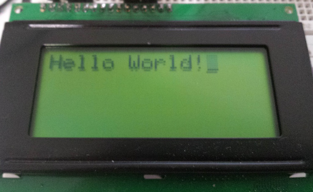 Hello World! written to EEPROM then read back and displayed on the LCD
|
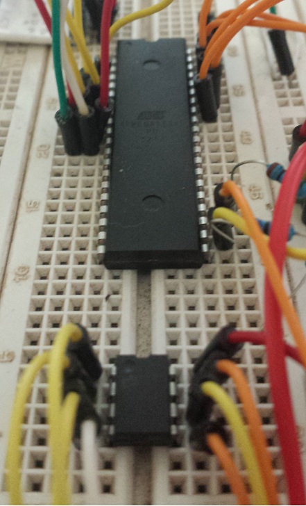 The ATMEGA and the EEPROM on heh Breadboard |
Stay tuned for part two in which a Slave Transmitter and Slave Receiver mode will be implemented.
Chris