Hi All!
Just a quick update here, code and STL’s for my 3D printed hexapod project can now be found on thingiverse:
http://www.thingiverse.com/thing:1814185
And on my github at
https://github.com/c-herring/HeZapod
-Chris
Hi All!
Just a quick update here, code and STL’s for my 3D printed hexapod project can now be found on thingiverse:
http://www.thingiverse.com/thing:1814185
And on my github at
https://github.com/c-herring/HeZapod
-Chris
Hey Everyone!
I have been working on a library to interface with a Playstation 2 controller using my Raspberry Pi. Raspberry Pi is an amazing brain for any robot so having a nice convenient way to interface with a wireless PS2 remote can make an awesome addition to any robot. I will be using it for my Pi controlled hexapod. Currently there is no functionality to enable rumble, I will hopefully be adding that soon. Also, obtaining the game controller state is kind of crude as you just need to access the public PS2data[] uint8_t array from the object. That will probably change soon too; but other than that it is working great.
You can find the most recent version at my github:
https://github.com/c-herring/PiPS2
And here is a video with a quick overview and some fun servo control:
– Chris
So I was not planning on calibrating all of the legs until I have my Raspberry Pi code all running great – but this thing so just too much fun to play with so I went ahead and done the calibrations. Whilst I was there I also cleaned up the wiring a great deal.
So all in all it is running absolutely amazing now so I thought I would share this quick update.
–Chris
So I finally finished printing, assembling and programming my fully 3D printed hexapod robot. It all came together quite nicely, I am however re-printing the tibias to be 160mm instead of 100mm as they are now. In my initial design I envisioned having horizontal femurs and vertical tibias to give the robot much more of a “robotic” look, as opposed to the more common inset/spider kind of aesthetics that lots of other hexapods go for. So this meant having tibias at around the same length as the femur. It all runs great however I am going to opt for longer tibias – I have decided that I like the insect look better and longer tibias can also give me a longer stride so there will be more versatility with walking gaits.
Once I smooth out the design and maybe re-design the chassis to give a bit more structural integrity; along with some more thought out mounting space for the battery (zero thought was given to that at this point); I will be posting the full build instructions and 3D models both here and on thingiverse, so stay tuned for that!
— Chris
I made a couple of videos to help introduce and explain the incredibly counter-intuitive concept of Gyroscopic Motion to students in a 3rd year Mechanical Engineering unit that I am a Teaching Assistant for at UWA. A small part of the explanation is in the context of the material provided in the unit, however all of the information that you need to form a basic understanding is present. Hopefully this can help others get their head around this crazy concept, I know it took me a little while to understand it when I first encountered it.
The maths is actually really simple with a basic high school understanding of vectors. So just keep that in mind. Don’t try and understand WHY it moves like it does, it is way too counter-intuitive for that and you will just get confused. Rather, try to understand WHY the MATHS says that it moves like it does. Then you can confirm that the maths agrees with reality.
This is a basic introduction to Gryoscopic Motion by looking at the motion of a top spinning with constant angular velocity, at an angle from horizontal.
A more in depth look at Gryoscopic motion. Euler’s equations for rotational motion, their derivation and simplifications that can be made; along with how they can be applied to the spinning top problem.
–Chris
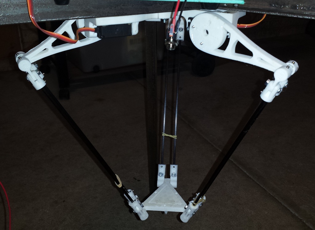
Here is a small side project that I have been working on as part of my larger Hexapod project. For my Hexapod I am using Hitec HS-485 servos which have their axis supported by a bearing. So radial loads are well supported and there is very little thrust load to worry about. However there is some torsional load required to support the weight of the body and to keep the legs rigid. Many higher end servos counter this by providing an idle bearing on the opposite side, there are also various brackets available which provide this idle bearing to lower range servos. But why spend $5 on a bracket when you have a 3D printer?
Hello Everyone, I bring to you a tutorial on how the AVR TWI module operates. This is part 1 of the tutorial and deals with Master Transmitter and Master Receiver mode. Stay tuned for part 2 which will build on this to add Slave Receiver and Slave Transmitter functionality.
I2C (Inter Integrated Circuit) or TWI (Two Wire Interface) is a half duplex serial two wire interface for interconnecting low to medium speed peripherals. It uses two open drain signal lines, Serial Data (SDA) and Serial Clock (SCL). As these are open drain lines the device may sink however it cannot drive a line high. In order to allow for high signals the lines must be pulled high using a pull-up resistor. The bus drivers of all TWI compliant devices are open drain and this is essential to the operation of the interface.
TWI is a master/slave protocol. Multiple masters are allowed however only one device may be master at any one time.
The ATMEGA and ATTINY range of ATMEL MCU’s (along with the majority of other ATMEL MCU’s) have a dedicated TWI bus interface which takes care of START/STOP conditions, SCL clock, arbitration and address detection. They also have dedicated shift registers for sending and receiving data on the bus. The TWI pins also have slew rate limiting and a spike detection to remove spikes shorter than 50ns. The internal pull ups can be enabled by setting the PORT bits on the SDA and SCL pins to high.
I will first provide an overview of the TWI interface, followed by an overview of the AVR TWI hardware before I get into designing the interrupt driven TWI library.
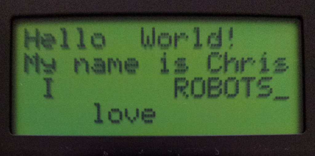
I would like to add an alphanumeric display to my AVR projects. I picked up this FDCC1604A 16×4 alphanumeric display from RS components.
I now require a library to simplify use over a variety of ATMEL based applications.
Continue reading
 Desktop 3D printers have come a long way in the past several years. The RepRap community provides open source designs for Fused Deposition Modelling printers. This makes it possible to construct a high quality desktop 3D printer for under $1000
using only a small number of specialized parts (ie. filament extruder components).
3D printers introduce the possibility of fabricating precision parts in a timely and – most important – reliable manner. What would usually take hours to fabricate in the workshop can now be printed, still in a couple of hours, however all that need be done is draw a design in your favorite CAD program and send it off to print.
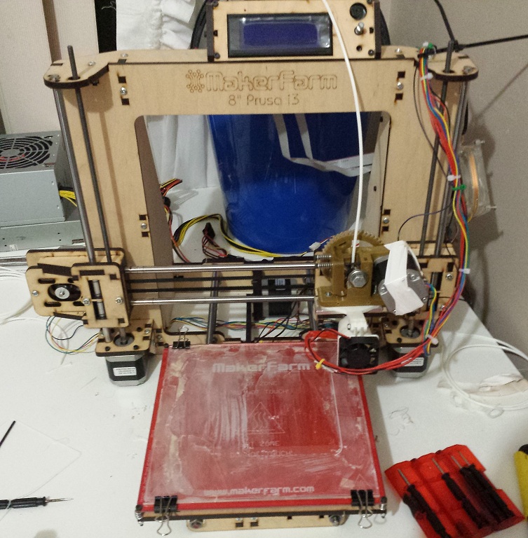
My love of mechatronics not only attracts me to the 3D printer itself, but the many possibilities for design and prototyping that it opens! For several years I have been building my RepRaps. Or I guess I should say RepStrap. I have been through a couple of Mendel variations which ended up leading me to a custom i3 design. At the end of exam period 2013 however I decided that I would go ahead and pull my existing printer apart and reassemble it into a delta design. So after printing all of the parts and being sure that I could assemble it first try – I went for it. That was a mistake. Several parts were missing and when attempting reassemble my i3 I broke a z-carriage. So now I was left with a broken printer, no spares and no printer to print a spare. Lesson learned – ALWAYS have a full set of spares – especially if you are planning on completely disassembling your printer.
Well, I print everything. So many useless robots that have a lifespan of a week before they are torn apart harvested for their components and a new one is printed. So I may aswell just bite the bullet and spend some money and get a kit, right?
After extensive research into the many RepRap designs and kits out there, I decided on the wood base Prusa i3 from MakerFarm.
Currently, the project is operational, all parts have bfeen printed and assembled. The main controller is an Atmel ATMEGA328P micro controller which interfaces
via I2C with a PCA9685 PWM controller to set servo positions. Positional data is sent to the controller via a BC417 bluetooth module.
A Windows based control program has been written in C++/CLI.